Sunday 28 April 2024

(Fixed) VVDI PROG Read NEC3529 Prompts "Adapter invalid"

A few days ago we received a case sharing from a customer about the solution to "VVDI PROG read NEC3529 prompts 'Adapter invalid' ".

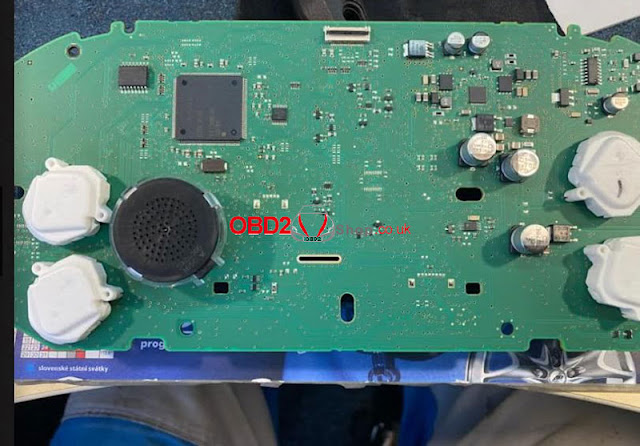
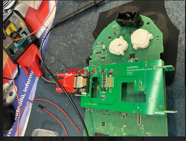
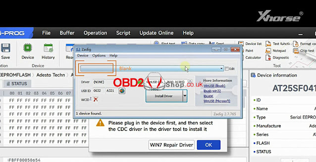
Customer's problem: I tried to read the NEC3529 using the XDNP82 adapter and the software still tells me that the adapter is invalid, look at the picture.

all contacts are ok, also on FLMD 3.3V

vvdi-prog-read-nec3529-prompts-adapter-invalid-1

vvdi-prog-read-nec3529-prompts-adapter-invalid-2

vvdi-prog-read-nec3529-prompts-adapter-invalid-3

Later, the customer found the problem himself and successfully solved it:

Problem solved!

The adapter does not work at a voltage of 12V.

The voltage on the power supply must be at least 12.5 V.

Thanks to Jan Sima for sharing with us.

For more technical support, please follow www.obd2shop.co.uk

Sunday 28 January 2024

How to install Xhorse Multi-prog Driver on WIN7

In the previous article, we briefly introduced the Xhorse Multi-prog Programmer. Today, we will guide you on how to install the driver for your Multi-prog device upon receiving it, so you can successfully utilize it.


If you have received the Multi-prog but find that there is no response when connecting to the computer, and the software shows that the device is not connected, don't worry.

This is not a problem with the device. Likely, you haven't installed the driver yet.


If your computer is a WIN10 system, the driver will be installed automatically, so you don't have to worry about it.


However, if your computer is a WIN7 system, we need to install the driver manually.


So today I will show you how to install the driver for Multi-prog manually.


First, connect the device to the computer, then click [Help] on the top of the software interface.

how-to-install-xhorse-multi-prog-driver-on-win7-1

how-to-install-xhorse-multi-prog-driver-on-win7-2

Choose [Install the driver] and there will be a popup.

The device name will be automatically identified here.

If it is blank, it means that the device is not recognized and we need to re-plug the device or change the port until a multi-prog device appears here.

how-to-install-xhorse-multi-prog-driver-on-win7-3

how-to-install-xhorse-multi-prog-driver-on-win7-4

Then click the small arrow to find the CDC driver.

Start the installation.

Okay, we can see that the device status becomes "connected".

how-to-install-xhorse-multi-prog-driver-on-win7-5

how-to-install-xhorse-multi-prog-driver-on-win7-6

how-to-install-xhorse-multi-prog-driver-on-win7-7

Please note that if the installation fails, we need to click [WIN7 Repair Driver] first, and then install the driver again.

how-to-install-xhorse-multi-prog-driver-on-win7-8

If you encounter any problems during the installation process, please contact technical support on Xhose APP or you can contact us.


For more technical services, please pay attention to http://blog.obd2shop.co.uk/

Wednesday 10 January 2024

VVDI2 + GODIAG Mech-Key Test Platform Read BMW CAS1

GODIAG BMW Mech-Key Test Platform is used for BMW CAS1/CAS2 mechanical key matching, reading, writing, and synchronization without welding. Compatible with most key programmers like Xhorse VVDI2, Key Tool Plus, etc. To program BMW semi-smart keys, we should use the GODIAG Semi Smart Test Platform.


Following we'll show how to read CAS1 data with VVDI2 + GODIAG.

1. Connect GODIAG, VVDI2 & CAS1 module.

2. Press the GODIAG START button to power it on.

3. Connect VVDI2 to the computer.

vvdi2-godiag-mech-key-test-platform-read-bmw-cas1-1

vvdi2-godiag-mech-key-test-platform-read-bmw-cas1-2

Open VVDI2 software, 

Key Learn >> CAS/EWS information >> Connect >> Read EEPROM >> OK

Reading data success.

Save the EEPROM file.


Read KM >> OK

The kilometer stored in CAS is 271905km.


Read Code >> OK

CAS code-DME: 3926

All reading success.

vvdi2-godiag-mech-key-test-platform-read-bmw-cas1-3

vvdi2-godiag-mech-key-test-platform-read-bmw-cas1-4

vvdi2-godiag-mech-key-test-platform-read-bmw-cas1-5

Insert the key into the ignition for a test.

The key is NOT ejected, which means key info is synchronized.

Key Learn >> CAS Key Learn >> Connect >> Get key info >> Add key >> OK

We can see the key has occupied the Key7 position.

Save the original key file.

Done.

vvdi2-godiag-mech-key-test-platform-read-bmw-cas1-6

vvdi2-godiag-mech-key-test-platform-read-bmw-cas1-7

vvdi2-godiag-mech-key-test-platform-read-bmw-cas1-8

www.obd2shop.co.uk

Sunday 7 January 2024

Xhorse Multi-Prog Read/Write Microcontroller Operation Guide

This is an operation guide on how to read & write Microcontroller via Xhrose Multi-Prog Programmer. Read this article carefully to learn.

xhorse-multi-prog-read-write-microcontroller-operation-guide-1

Why to read & write Microcontroller?

The microcontroller function is mainly used for data reading and writing of various automotive electronic modules and automotive computer modules. It is especially suitable for automobile circuit module repair. Before using this function, you need to understand some principles and common knowledge of microcontrollers.


Multi-PROG supports reading, writing, and programming various common brands of microcontrollers. Before data reading and writing, you should make the correct wiring connections according to the software wiring diagram corresponding to the brand, model, and microcontroller series. For some models, the microcontroller requires a soldering minimum system circuit before reading.


How to distinguish Microcontroller manufacturers?

Xhorse Multi Prog device supports reading and writing microcontrollers from multiple manufacturers. Among common automotive electronic modules, the microcontroller manufacturers used include Atmel, Motorola, Freescale, Infineon, Renesas, STMicroelectronics, etc. As shown in below pic.

xhorse-multi-prog-read-write-microcontroller-operation-guide-2

What's the Microcontroller memory area division?

Microcontroller usually has three storage spaces: program area, data area, and configuration area. The program area stores the program data of the microcontroller. The data area stores the information data of the microcontroller. The configuration area stores the corresponding configuration data of the microcontroller, such as the encryption byte option, the startup byte option, and so on. When reading and writing microcontroller data, it is necessary to distinguish by different areas. In software, names such as FLASH, CFLASH, CODE, and ROM are usually used to represent the program area. The names such as DFLASH, EEPROM, DATA, INF, etc. represent the data area. The names such as Config represent the configuration area. Please note that the configuration area may be unreadable for encrypted chips.


How to read & write Microcontroller?

The microcontroller option provides wiring diagrams for the basic read/write of the corresponding microcontroller. During the actual read/write process, a multimeter is necessary to find the connection diagram for the specific board, as shown in the below pic.


1)Optional(must be low): When reading this microcontroller, you must make sure that this pin of the board is low before you can read it. If it is not low, you can connect a 1K pull-down resistor to GND on this pin.

2)Pull-up resistor: This pin needs to be connected to a pull-up resistor to VCC when reading.

3)If the crystal frequency is not 4 megahertz, please connect pin 1 of the chip to the CLK output of the programmer: When reading, this pin needs to be checked whether it is necessary to connect an external clock pin for reading.

xhorse-multi-prog-read-write-microcontroller-operation-guide-3

www.obd2shop.co.uk